
| Object Detection | |
The operator detects object such as ships on sea surface from SAR imagery.
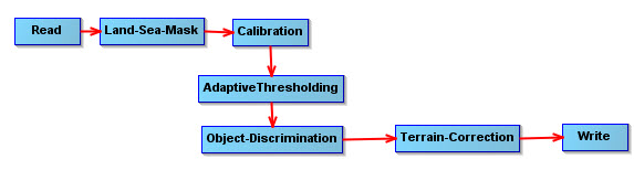
The object detection operation consists of the following four major operations:
For details of calibration, the reader is referred to the Calibration operator. Here it is assumed that the calibration pre-processing step has been performed before applying object detection.
For details of land-sea mask generation, the reader is referred to the Create Land Mask operator.
The detector used in pre-screening operation is the two-parameter constant false alarm rate (CFAR) detector. The basic idea is to searche pixels which are unusually bright when compared to pixels in surrounding area.
Let x t be the pixel under test and T be a given threshold, then the detection criterion can be expressed as
Let f(x) be the ocean clutter probability density function and x range through the possible pixel values, then the probability of false alarm (PFA) is given by
and the above detection criterion is equivalent to the criterion below
If Gaussian distribution is assumed for the ocean clutter, the above detection criterion can be further expressed as
where μb is the background mean, σb is the background standard deviation and t is a detector design parameter which is computed from PFA by the following equation
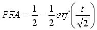
The valid PFA value is in range [0, 1].
In real implementation of the two-parameter CFAR
detector, a setup shown in Figure 1 is employed. The
target window contains the pixel under test, the background
“ring” contains pixels for estimating the
underlying background statistics while the guard “ring”
separates the target window from the background ring so
that no pixels of an extended target are included in the
background ring. The background mean μb and the standard deviation
σb used in the criterion are estimated
from the pixles in the background ring.
In case that the target window contains more than one pixels, this operator uses the following detection criterion

where μt is the mean value of pixels in the target window. In this case, t should be replaced by t√n (where n is the number of pixels in the target window) in the PFA calculation.
The object detection is performed in an adaptive manner by the Adaptive Thresholding operator. For each pixel under test, there are three windows, namely target window, guard window and background window, surrounding it (see Figure 1).
Normally the target window size should be about the size of the
smallest object to detect, the guard window size should be about
the size of the largest object, and the background window size
should be large enough to estimate accurately the local
statistics.
The operator
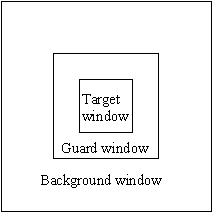
Figure 1. Window setup for adaptive thresholding algorithm.
The discrimination operation is conducted by the Object Discrimination operator. During this operation, false detections are eliminated based on simple target measurements.
For Adaptive Thresholding operator, the following parameters are used (see Figure 2):
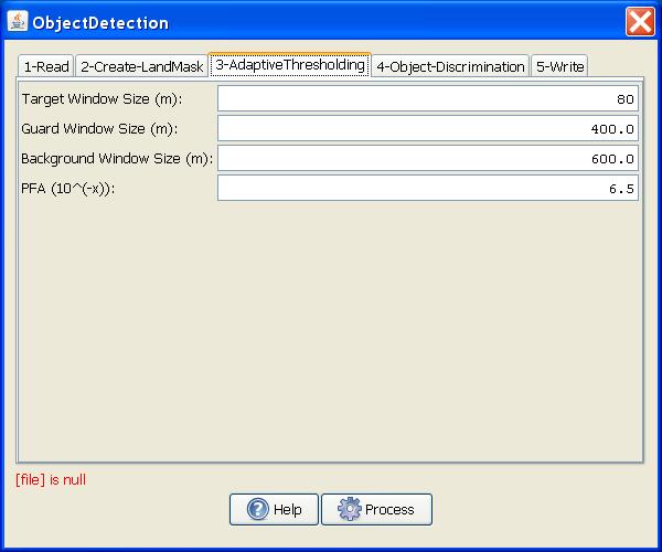
Figure 2. Adaptive Thresholding
Operator dialog box.
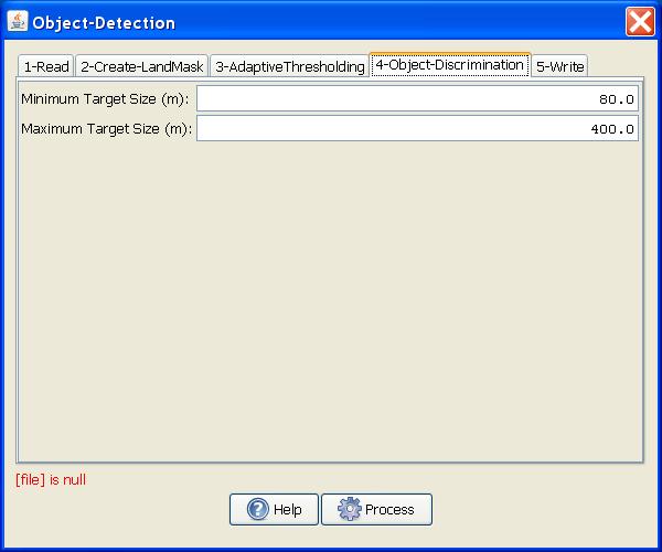
For Object Discrimination operator, the following parameters are used (see Figure 3):
Minimum Target Size (m): Target with dimension smaller than this threshold is eliminated.
Maximum Target Size (m): Target with dimension larger than this threshold is eliminated.
To view the object detection results, the following steps
should be followed:
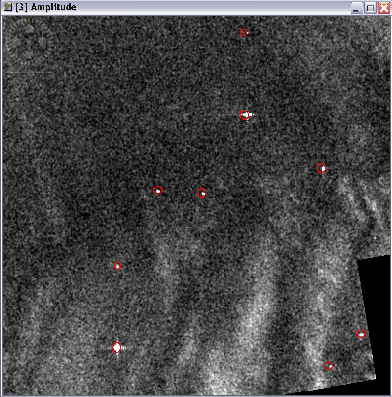
The detected object will be circled on top of the image view (see example in the figure below). An Object Detection Report will also be produced in XML in the .s1tbx/log folder.
Reference:
[1] D. J. Crisp, "The State-of-the-Art in Ship Detection in Synthetic Aperture Radar Imagery." DSTO–RR–0272, 2004-05.