Wind Field Estimation
As the wind blows across the ocean surface, it
generates surface roughness generally aligned with the wind
direction. Consequently the radar backscatter from this roughened
surface is related to the wind speed and direction. This operator
retrieves wind speed and direction from C-band SAR imagery.
Major Processing Steps
The general approach for the wind field retrieval is as
the follows:
- First a land-sea mask is generated to ensure that the
estimation is focused only on the sea surface area.
- Then the SAR image is divided into grid using user specified
window size.
- For each grid, a wind direction (with 180� ambiguity) is
estimated from features in the SAR image using a frequency
domain method.
- With the wind direction estimated for the grid, finally the
wind speed is estimated by using CMOD5 model for the Normalized
Radar Cross Section (NRCS).
For details of land-sea mask generation, the reader
is referred to the
Create
Land Mask
operator.
Wind Direction Estimation
The wind direction is estimated from the features in
the SAR image. Detailed steps for the estimation are given
below:
- For each window within which a wind direction will be
estimated, a local FFT size is determined. The FFT size is 2/3 of
the window size, therefore four spectra can be computed in the
window with each spectra region has a 50% overlap with the
neighboring spectrum.
- Each window is flattened by applying a large average filter,
then dividing by the filtered image.
- The FFT’s are applied and the four resulting spectra are
averaged.
- An annulus is applied to the spectrum to zero out any energy
outside of a wavenumber region. The limits of the annulus are set
to wave lengths of 3 km to 15 km.
- A 3x3 median filter is then applied to the spectrum to remove
noise.
- A 2D polynomial is fit to the resulting spectral samples and
the direction through the origin which has the largest quadratic
term (i.e. the widest extent) is determined. The wind direction is
then assumed to be 90 degree from this direction.
Wind Speed Estimation
- The wind speed is estimated using the CMOD5 model
for NRCS developed by Hersbach et
al. [1] for VV-polarized C-band scatterometry.
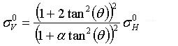
- For ENVISAT HH-polarized product, where CMOD5
model is not directly applicable, the operator first converts the
NRCS at HH polarization into a corresponding NRCS for VV
polarization with the following equation, then applies the CMOD5
model to the converted NRCS:
where θ is the incidence angle and α is set
to 1.
For details of the CMOD5 model, the readers are
referred to [1].
Products Supported
- The operator now is only supported for ERS and
ENVISAT (VV- and HH-polarized) products. The source product is
assumed to have been calibrated before applying the operator.
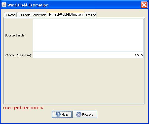
Parameters Used
The following parameters are used by the
operator:
- Source Bands: All bands (real or virtual) of the source
product. User can select one or more bands for producing
multi-looked images. If no bands are selected, then by default all
bands are selected.
- Window Size: The dimension of a window for which wind direction
and speed are estimated.
Figure 1.
Wind Field Estimation dialog box
Visualize Estimated Wind Direction
To view the estimated wind directions, the
following steps should be followed:
- Bring up the image.
- Go to layer manager and add layer called "Wind Field Estimation
Results".
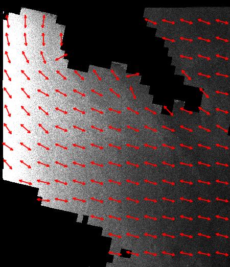
Then wind directions will be displayed as shown
in the example below. Note that the wind direction is indicated by
double headed arrows because a 180� ambiguity exists in the
estimated wind direction. Also for those grids in which land pixels
are found, the wind directions are not estimated and hence not
displayed.
Figure 2.
Example of wind direction display
Wind Field Retrieval Result Report
The wind field estimation results are saved
into an xml file .s1tbx/log/wind_field_report.xml with the
following information given for each window in which wind
estimation is made:
- lat: Latitude of the
central point in the window.
- lon: Longitude
of the central point in the window.
- speed: Estimated wind
speed in m/s.
- dx: X component of the
estimated wind vector.
- dy: Y component of the
estimated wind vector.
- ratio: In estimating
wind direction, the spectrum of a given window is matched with a 2D
polynomial (like f(x,y) = ax2 + bxy + cy2 +
dx + ey +f). The ratio in the report is the ratio of the minor semi
axes over the major semi axes of the 2D polynomial. Generally
speaking, the smaller the ratio value, the more reliable the
estimated wind direction.
Reference:
[1] H. Hersbach, CMOD5, “An Improved Geophysical Model Function
for ERS C-Band Scatterometry”, Report of the European Centre
Medium-Range Weather Forecasts (ECMWF), 2003.
[2] C. C. Wackerman, W. G. Pichel, P. Clemente-Colon, “Automated
Estimation of Wind Vectors from SAR”, 12th Conference on
Interactions of the Sea and Atmosphere, 2003.